Linkage and Mechanism Simulator, Explained
After reading this you will know how a four-bar linkage turns rotary motion into a traced curve, how to predict whether a crank spins all the way round or locks up, and how to read the transmission angle so your design does not jam.
What a linkage is and one curve worth seeing
A planar linkage is a set of rigid bars joined by pin joints, laid flat so every joint moves in one plane. Fix a few joints to the ground, drive one bar with a motor, and the rest of the bars swing to whatever positions keep every bar at its fixed length. The whole machine has exactly one degree of freedom: turn the crank one degree and every other joint has exactly one place to go.
The hook is the coupler curve. Take the classic four-bar crank-rocker with ground pivots 30 units apart, a crank of length 10, a coupler of 35 and a rocker of 30. Mark a point on the coupler bar, not on either pivot, and turn the crank once. That point does not trace a circle or an ellipse. It traces a lopsided closed loop, a sextic curve, that can hold nearly straight segments, sharp cusps or figure-eight crossings depending on where you put the marked point. One bar, one motor, and you get a shape no single rotating part could draw.
When to reach for this, and when not
Use the simulator when motion is the point: you want a gripper that stays level, a wiper that sweeps an arc, a leg that lifts and swings, or a point that travels in a straight line without a rail. It answers geometric questions exactly. Where does joint D go when the crank is at 73 degrees? Does the output bar reach 90 degrees before the mechanism binds?
Do not use it for force, stress or speed under load. The solver places joints to satisfy length constraints. It does not compute the torque the motor needs, the stress in a bar, or whether a thin link buckles. For member forces in a loaded structure, the Bridge Builder and Truss Simulator is the right tool. For rotary power transmission through teeth rather than bars, see the Gear Generator.
The constraint that drives everything
Every bar imposes one equation: the distance between its two joints never changes. For a bar between joints A and B with fixed length L:
Here (x_A, y_A) and (x_B, y_B) are the joint coordinates and L is the bar length you typed in. Ground pivots fix two coordinates each. The crank angle, set by the motor, fixes the crank tip. What remains is a small system of quadratic equations in the free joint coordinates, and the solver finds a root with Newton iterations each frame.
Because the equations are quadratic, they usually have two solutions: the mechanism can assemble in two mirror poses, called branches. The solver starts each frame from the previous pose, so it stays on the branch you are already on. That is why a mechanism can look stuck halfway: it has run into the point where the two branches meet, and there is no nearby solution to step to.
Grashof's rule: will the crank go all the way round?
For a four-bar, one simple inequality decides whether any bar can rotate a full 360 degrees. Sort the four lengths. Call the shortest s, the longest l, and the other two p and q.
If this holds, the linkage is a Grashof mechanism and at least one bar turns fully. Which bar turns depends on which one is the ground. If the inequality fails, every bar can only rock back and forth: a non-Grashof four-bar, a triple-rocker.
When s + l = p + q exactly, the linkage is at the Grashof boundary. At certain crank angles all four joints line up, both branches touch, and the mechanism can flip to the other branch unpredictably. Avoid designing right on this line unless you want that behavior.
A worked example: the demo four-bar
Crank-rocker with lengths 10, 35, 30, ground 30
Load the default four-bar. Ground pivots sit at A = (0,0) and D = (30,0). The crank AB has length 10, the coupler BC length 35, the rocker CD length 30.
- Check Grashof. Sorted lengths are
10, 30, 30, 35, so s = 10, l = 35, p = q = 30. Test: 10 + 35 = 45 and 30 + 30 = 60. Since 45 \le 60, it is Grashof. The shortest bar is the crank, so the crank rotates fully: a crank-rocker. - Place B at crank angle 60 degrees. B = (10\cos 60^\circ, 10\sin 60^\circ) = (5, 8.66).
- Find C. It lies 35 from B and 30 from D. Solving the two distance equations gives C \approx (28.3, 29.4) on the upper branch.
- Read the rocker angle. The vector from D to C is (28.3 - 30,\ 29.4 - 0) = (-1.70, 29.4), which points at about 93.3^\circ from the positive x axis. That is the output angle for this one input.
Step the crank through a full turn and the rocker swings between two extremes, its stroke, while the crank spins freely. Mark the midpoint of the coupler and you get the coupler curve.
The input-output relationship is the heart of the design. Here is the rocker angle as the crank goes once around.
Transmission angle: how force gets through
The transmission angle \mu is the angle between the coupler and the output link at the joint where they meet. It measures how much of the force pushed along the coupler actually turns the output, versus how much just tries to stretch or compress the output bar.
In the common form for a four-bar, a and b are the coupler and output lengths, c is the crank, d is the ground, and \theta is the crank angle. The exact expression depends on which bars you label, but the meaning does not change: when \mu is near 90 degrees force transfers well, and when it drops toward 0 or 180 the output barely moves for large coupler force, so the mechanism jams and the motor torque spikes.
Keep the minimum transmission angle above about 40 degrees across the whole crank rotation. If the plot dips to 20 degrees anywhere, the mechanism will feel stiff and may stall there under real load, even though the pure geometry still solves.
Straight lines, inversors and walking legs
Some linkages are famous for the curves they draw. Chebyshev's linkage traces a path that is nearly straight over the middle of its stroke, with error of a fraction of a percent of the link length. Watt's linkage does the same with a different bar count and was used to guide steam engine pistons. Both only approximate a line.
The Peaucellier-Lipkin inversor is different. It draws an exactly straight line from pure pin joints, with no sliding guide, by using a geometric inversion. The product of the distances from a fixed point to two of its joints stays constant, which turns a circle into a straight line. It was the first linkage proven to do this exactly, in 1864.
Theo Jansen's Strandbeest leg is an eight-bar mechanism tuned so the foot traces a flat bottom and a high lifted return, a gait. Link the demo leg to the crank and the foot path looks like a rounded triangle: it stays level along the ground, then lifts clear on the way back. Chain several legs on one crankshaft at different phases and the whole machine walks.
Common mistakes
The first mistake is building a non-Grashof linkage and then wondering why the crank stops. Run the Grashof check before you animate. If s + l \gt p + q, no bar turns fully, and a motor on any bar will drive it into a dead point and reverse.
The second is ignoring the transmission angle. A mechanism can pass the Grashof test and still have a spot where \mu falls to 10 degrees. The geometry solves there, but a real build jams. Always scan the transmission angle plot across the full turn, not just at one pose.
If the mechanism suddenly flips to a mirror image mid-animation, you have crossed a branch point where both assembly solutions meet. The solver followed the only root available. Fix it by changing a link length so the mechanism never reaches that singular configuration, or by designing a Grashof linkage that stays clear of its dead points.
Related tools on this site
Once your motion is right, other simulators handle what a linkage cannot. The Gear Generator designs the meshing teeth that might drive your crank. The Topology Optimizer grows the stiffest bar shape for a given load and support, useful once you know the forces. For a drive motor that must hold a target angle, the PID Controller Simulator shows how the loop settles. And if your mechanism is a folding arm trying to clear a doorway, the Will It Fit furniture planner solves the same kind of geometric reachability problem in three dimensions.
Frequently asked questions
Why does my crank get stuck partway round?
Either the linkage is non-Grashof, so no bar can turn fully, or you have reached a dead point where the crank and coupler line up and the output has no clear direction to move. Check the sorted lengths against s + l \le p + q. If that holds but it still sticks, look at the transmission angle plot for a value near 0.
What is a coupler curve?
It is the path traced by a point fixed to the coupler bar, the one bar that touches neither ground pivot. Unlike a point on the crank (a circle) or on the rocker (an arc), a coupler point traces a complex sextic curve that can include near-straight runs, cusps and loops. Marking different points on the same coupler gives a whole family of curves.
Does the simulator compute forces or just positions?
Positions only. It solves the length constraints to place every joint, which gives you motion, coupler curves and the transmission angle. It does not model mass, friction, motor torque or bar stress. Treat the transmission angle as a warning of where force transfer gets bad, not as a force calculation.
How close to a true straight line can a linkage get?
Chebyshev's and Watt's linkages are approximate: deviation is roughly 0.1 to 1 percent of a link length over the useful stroke, enough for many machines. The Peaucellier-Lipkin inversor is exact: its traced point lies on a perfect straight line for the entire range, limited only by how well the bars are made.
Why do two linkages with the same bar lengths behave differently?
Because which bar is the ground changes which bar rotates fully. The same four lengths can be a crank-rocker, a double-crank or a double-rocker depending on which bar you fix to the ground. The Grashof inequality tells you a full rotation exists; the choice of ground tells you where.
Related tools
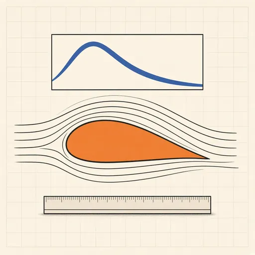
Airfoil Designer & Analyzer
Shape a NACA airfoil, see its pressure distribution and plot lift and drag polars, XFOIL-style, in the browser.
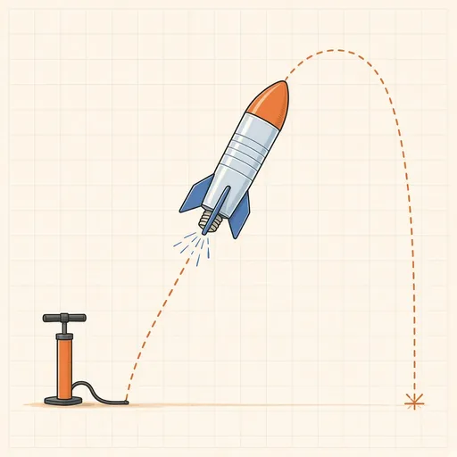
Bottle Rocket Simulator
Fill a soda-bottle water rocket, pump it up and launch it: find the water level, pressure and fins that fly highest.
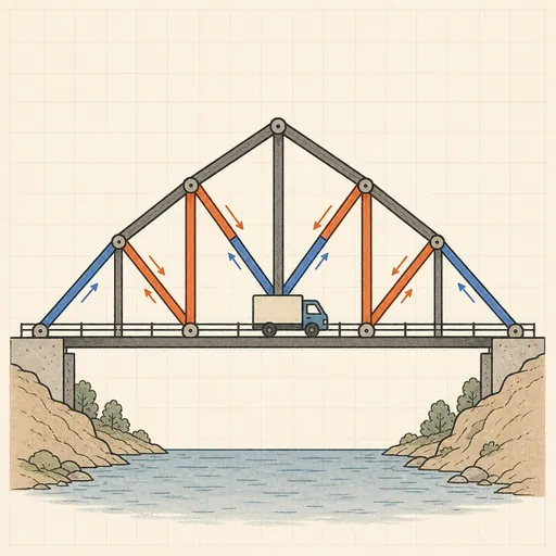
Bridge Builder & Truss Simulator
Design a truss bridge, send a truck across and watch every member strain, buckle or snap under load.
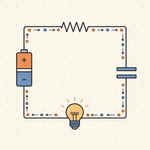
Circuit Simulator
Build analog circuits on a grid and watch current flow live — batteries, resistors, capacitors, LEDs and more.

Earthquake Shake Table Simulator
Shake a multi-story building with an earthquake and watch it sway, crack or survive, with base isolation and dampers.
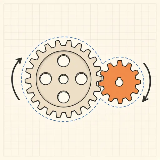
Gear Generator
Design involute spur gears, racks and planetary sets, watch them mesh and export SVG or DXF for laser cutting.