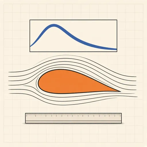
Airfoil Designer & Analyzer
Design a wing section and analyse it the way aerodynamicists do. Set a NACA 4-digit profile with camber, camber-position and thickness sliders, load a classic such as the 0012, 2412, 4412 or 23012, or paste coordinates in Selig .dat format from an airfoil database. A vortex panel method solves the flow around the shape: the pressure-coefficient curve, the streamlines and the lift and moment coefficients update as you drag the angle of attack. Set the Reynolds and Mach numbers and the tool sweeps the angle to plot the lift curve, the drag polar and the lift-to-drag ratio, with stall and drag estimated from boundary-layer rules of thumb. Export the coordinates as a .dat file or the profile as an SVG rib template at any chord length.
Runs 100% in your browser — simulations are computed locally on your device.
Notes
- The solver is a linear-strength vortex panel method with cosine-spaced panels and the Kutta condition at the trailing edge; lift comes from the circulation, so a thin symmetric section shows the textbook slope of about 2π per radian.
- Panel methods are inviscid: they get pressure and lift right below stall but cannot see drag or separation, so drag and the stall angle here come from skin-friction and empirical stall estimates, not from the flow solve.
- Camber shifts the whole lift curve up, giving lift at zero angle; thickness mostly buys a gentler stall and a stronger structure, at a small drag cost.
- Runs 100% in your browser — simulations are computed locally on your device.
Related tools
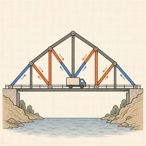
Bridge Builder & Truss Simulator
Design a truss bridge, send a truck across and watch every member strain, buckle or snap under load.
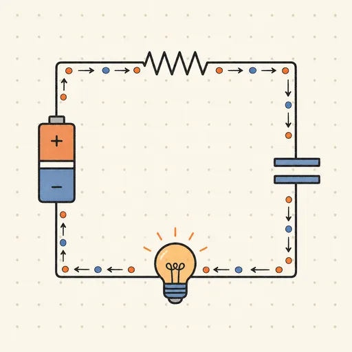
Circuit Simulator
Build analog circuits on a grid and watch current flow live — batteries, resistors, capacitors, LEDs and more.
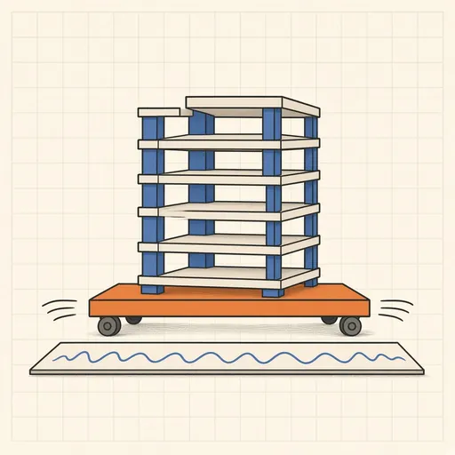
Earthquake Shake Table Simulator
Shake a multi-story building with an earthquake and watch it sway, crack or survive, with base isolation and dampers.
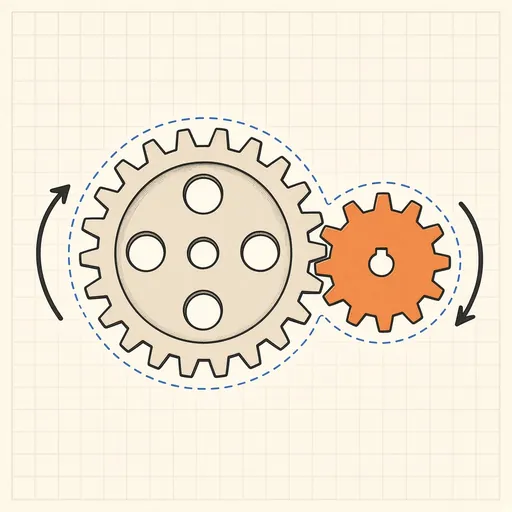
Gear Generator
Design involute spur gears, racks and planetary sets, watch them mesh and export SVG or DXF for laser cutting.
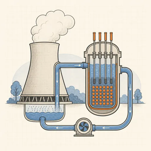
Nuclear Reactor Simulator
Run a pressurized-water reactor: pull control rods, manage xenon and temperature — or SCRAM before it overheats.
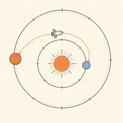
Orbital Mission Planner
Plan an interplanetary transfer: pick two planets, scan launch windows on a porkchop plot and fly the mission.