Topology Optimization, Explained
After reading this you will understand how a computer grows a stiff structure from a gray block, how the SIMP method decides where material belongs, and how to read the stress, deflection and mass numbers without being fooled by them.
What topology optimization does
You start with a rectangle of material, a few points where it is bolted down, and a place where a load pushes on it. You do not draw a shape. The computer draws the shape for you by keeping material where it carries load and deleting material where it does not.
The classic result is a bracket that looks like bone. Give the solver a block held on its left edge with a downward force on the bottom-right corner, ask it to keep only 40% of the material, and it will carve out a fan of diagonal struts that meet the support like the trabeculae in the head of a femur. Nobody designed that pattern by hand. It falls out of one rule: put material where removing it would cost the most stiffness.
The measure being optimized is compliance, the work the load does as the part deflects. Low compliance means high stiffness. A part with compliance 0.5 J is twice as stiff as one at 1.0 J under the same load. The solver drives that number down, iteration by iteration, while never using more material than your budget allows.
When to use it, and when not to
Use topology optimization when you know the loads and supports and you want the lightest part that meets a stiffness target: a mounting bracket, a lever, a machine frame node. It is at its best early in design, before you have committed to a shape, when the answer to "where should the material go" is genuinely open.
Do not trust it as a finished part. The result here is a 2D plane-stress optimum for one load case and a linear-elastic material. Real parts see several load cases, fatigue cycles, buckling, and the blunt limits of how you actually make the thing. A truss that is optimal in pure tension can fail by buckling at a tenth of that load. If you want to feel how members buckle and snap under a moving load, the Bridge Builder & Truss Simulator is the honest companion to this idealized picture.
A single-load-case optimum is fragile. Push on the same bracket from a different direction and the elegant diagonal struts may carry almost nothing. Always ask whether your real part sees only the one load you optimized for.
The math: SIMP and compliance
The design space is cut into a grid of small square finite elements. Each element e gets a density variable x_e between 0 (void) and 1 (solid). The trick that makes the whole thing work is how stiffness depends on that density:
Here E_0 is the Young's modulus of the solid material, and p is the penalty exponent, usually 3. This is SIMP: Solid Isotropic Material with Penalization. With p = 3, an element at half density x_e = 0.5 gives you only 0.5^3 = 0.125 of the stiffness while still spending 0.5 of the material budget. Gray is a bad deal. The optimizer is pushed toward crisp black-and-white designs because half-filled material is uneconomical.
The problem being solved each step is: minimize compliance
subject to a volume constraint \sum_e x_e v_e \le V. Here \mathbf{U} is the vector of node displacements, \mathbf{K} is the global stiffness matrix, \mathbf{u}_e is the displacement of element e, and \mathbf{k}_0 is the element stiffness of solid material. The tool solves \mathbf{K}\mathbf{U} = \mathbf{F} for \mathbf{U} every iteration with a banded Cholesky factorization, then computes how much each element's density helps.
That help is the sensitivity, the derivative of compliance with respect to density:
It is always negative: adding material always lowers compliance. The optimizer wants to move density toward elements where this derivative is most negative, meaning the elements carrying the most strain energy. The optimality-criteria update does exactly that, then a bisection on the volume constraint's Lagrange multiplier scales everything so the budget is met exactly.
Why the filter is not optional
If you optimize the raw densities directly, you get a checkerboard: alternating full and empty elements that a finite-element mesh reports as artificially stiff. It is a numerical artifact, and it gets finer as you refine the mesh, so the "optimum" depends on your grid. That is an ill-posed problem.
The fix is a density filter. Before computing sensitivities, each element's value is blended with its neighbors inside a radius r_{min}, weighted by distance:
where d_{ei} is the distance from element e to neighbor i. The filter sets a length scale: no strut can be thinner than about r_{min} elements. Set r_{min} = 1.5 and you get many thin members; set it to 4 and you get a few fat ones. The filter is what makes the answer stable and manufacturable.
Worked example: the Cantilever preset
Pick the Cantilever preset and you get a rectangular block, 92 by 46 elements at standard resolution, clamped along its left edge, with a downward point load at the middle of the right edge, penalty p = 3, and a volume budget of 40%. Here is what the compliance does as it iterates.
- Iteration 0 starts fully gray at x_e = 0.4 everywhere so the budget is already met. Compliance is high because gray material at 0.4^3 = 0.064 stiffness is soft.
- The first few updates dump material into the top and bottom edges, where bending stress is largest. Compliance drops fast: from 622 to 120 in the first 10 iterations.
- Diagonal struts form to carry shear toward the support. The design is still partly gray, so the SIMP penalty keeps squeezing it toward solid-or-void.
- After about 30 iterations the compliance barely moves, but the edges of the struts keep sharpening. The solver stops when no element changes by more than
0.01in a step, here at iteration 160. What remains is a black truss on a white background.
This run drives compliance from 622 down to 85 in the tool's dimensionless units, about seven times stiffer than the uniform gray start for the same 40% of material. The exact numbers depend on mesh size, but the shape of the curve is always this steep-then-flat descent.
Reading the results honestly
Once a shape converges, the tool reports real-world numbers for your chosen material. These come from scaling the dimensionless optimum by the material's modulus and your part dimensions. Three numbers matter.
- Maximum stress
- The highest von Mises stress in the part. Compare it to the material's yield strength. PLA yields near
50MPa, aluminium 6061-T6 near270MPa, mild steel near250MPa. If the reported stress exceeds yield, the part fails even though the optimizer was happy. - Deflection
- How far the load point moves. This is compliance made physical. A stiffer optimum deflects less.
- Mass
- Volume of solid material times density. PLA is about
1240kg/m³, aluminium2700, steel7850. Steel is roughly six times denser than PLA, so the same shape in steel is six times heavier but far stiffer.
Here is the point the optimizer will not tell you: compliance minimization ignores stress. It minimizes total strain energy, not peak stress. So the optimal shape often has sharp reentrant corners where struts meet, and those corners concentrate stress. A design that is 4 times stiffer overall can still have a stress spike at one joint that fails first. Always check the stress view, not just the deflection.
Switch to the stress view and look at the joints where struts meet. If one corner glows far brighter than the rest, add a fillet in your CAD step or increase the filter radius to fatten the members before you trust the mass number.
Explore the penalty exponent
The single most instructive parameter is the SIMP penalty p. It controls how hard the optimizer punishes gray material, and therefore how sharp the final design is.
Common mistakes
The volume budget is a hard constraint, not a target you approach. If you ask for 40%, the optimizer spends exactly 40% every single iteration. Asking for less material does not always give a lighter useful part: below some threshold the struts get too thin to carry the load and the deflection blows up. Watch the deflection number as you lower the budget.
A filter radius that is too small brings back checkerboarding and mesh dependence. Too large a radius washes out all the fine structure into one blob. Start near 1.5 to 3 element widths and adjust once.
Do not read the dimensionless compliance as a physical quantity. It is only meaningful relative to other runs on the same mesh and load. The real-world stress and deflection numbers are the ones to compare against material limits.
Finally, the result is a 2D plane-stress slice. It assumes the part is a thin plate loaded in its own plane. A real 3D bracket loaded out of plane behaves differently, and no amount of 2D optimizing captures that.
Related tools
If you want to test a hand-designed truss against a moving load and watch members buckle, use the Bridge Builder & Truss Simulator. To see how a shape behaves in a moving fluid instead of under a static load, draw it into the Wind Tunnel (CFD Sandbox) and read off drag and lift. For a rocket where mass and structure trade against thrust, the Rocket Designer & Staging Lab shows the same lightness-versus-strength tension at vehicle scale.
Frequently asked questions
Why does my result look gray instead of black and white?
Either the penalty is too low or the solver has not converged yet. At penalty 1, gray material is not punished, so the optimum stays a smooth density field. Raise the penalty toward 3 and let it run more iterations. If it stays gray at penalty 3, your filter radius may be smoothing away the structure.
Can I trust the STL for a load-bearing part?
Not without more checks. The STL captures the stiffness-optimal shape for one 2D load case. Before you rely on it, verify peak stress against yield with a margin, check for buckling of slender members, and add fillets at the sharp joints the optimizer leaves behind.
Why does lowering the material budget sometimes make the part worse?
Compliance rises fast as the budget falls because struts thin out. Halving the volume from 40% to 20% can more than double the deflection. There is a point where the shape is optimal but simply too weak. Watch the deflection number, not just the shape.
What does compliance actually measure?
It is the work the load does as the structure deflects, equal to \mathbf{U}^{T}\mathbf{K}\mathbf{U}. Minimizing it is the same as maximizing global stiffness. A part at compliance 85 is about seven times stiffer than the same block at compliance 622, as in the worked example above.
Does the optimizer control stress?
No. It minimizes total strain energy, not peak stress. That is why an optimal shape can still have a dangerous stress spike at a joint. Always inspect the stress view separately.
Related tools
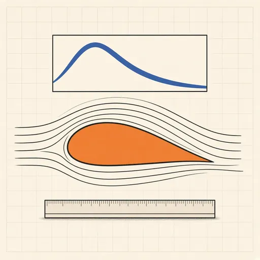
Airfoil Designer & Analyzer
Shape a NACA airfoil, see its pressure distribution and plot lift and drag polars, XFOIL-style, in the browser.

Bottle Rocket Simulator
Fill a soda-bottle water rocket, pump it up and launch it: find the water level, pressure and fins that fly highest.
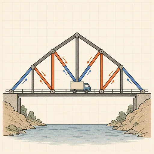
Bridge Builder & Truss Simulator
Design a truss bridge, send a truck across and watch every member strain, buckle or snap under load.
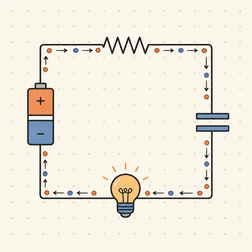
Circuit Simulator
Build analog circuits on a grid and watch current flow live — batteries, resistors, capacitors, LEDs and more.
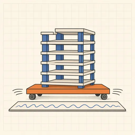
Earthquake Shake Table Simulator
Shake a multi-story building with an earthquake and watch it sway, crack or survive, with base isolation and dampers.
Gear Generator
Design involute spur gears, racks and planetary sets, watch them mesh and export SVG or DXF for laser cutting.