The Voltage Divider, Explained
After reading this you can predict the output voltage of any two-resistor divider, pick the R2 that hits a target voltage, and know when the simple formula stops telling the truth.
What a voltage divider does
A voltage divider is two resistors in series across a source. You tap the middle node to get an output voltage smaller than the input. The current that flows down through R1 also flows through R2, and the voltage splits between them in proportion to their resistances.
Here is the hook. You have a 12 V supply and a sensor that reads voltages only up to 5 V. Feed 12 V through 10000 Ω on top and 5000 Ω on the bottom, and the middle node sits at 4 V. The sensor is safe, and you did it with two cheap parts and no active components.
Dividers show up everywhere: setting a reference voltage, scaling a signal down before an analog-to-digital converter, biasing a transistor base, and reading a potentiometer. The idea is always the same. Two resistances, one ratio, one output.
When to use it, and when not to
A divider is the right tool when the thing you connect to the output draws almost no current compared to the divider itself. A microcontroller analog input, an op-amp input, or a comparator input all qualify: they draw nanoamps to microamps.
A divider is the wrong tool when you want to power something. It is not a regulator. If the load current changes, the output voltage moves with it, because the load current no longer flows only through R2. Trying to run a 100 mA circuit from a divider will collapse the output and waste power as heat.
Never treat a divider as a supply for a load that draws real current. The output voltage sags the moment the load pulls current comparable to the divider current. Use a regulator for power, a divider for reference and sensing.
The formula and why it works
The two resistors carry the same current because they are in series. That current is the input voltage divided by the total resistance:
Here V_{in} is the source voltage in volts, R_1 is the top resistor and R_2 is the bottom resistor, both in ohms, and I is the current in amperes. The output is the voltage across R2 alone, which by Ohm's law is I \cdot R_2. Substitute the current:
Every symbol keeps the meaning above. The fraction R_2 / (R_1 + R_2) is a pure ratio between 0 and 1. It says what share of the total resistance sits below the tap, and the output takes exactly that share of the input.
Two sanity checks. If R_2 = 0, the output is 0 V: the tap is shorted to ground. If R_1 = 0, the output equals V_{in}: the tap sits right at the source. Real dividers live between these extremes.
To solve the other direction, fix a target output and rearrange for R2. Starting from the output formula and solving:
This has a solution only when V_{out} \lt V_{in}. A passive divider can never raise a voltage, so a target at or above the input is impossible.
A worked example with the demo numbers
12 V into 10k over 5k
Use the tool defaults: Vin = 12 V, R1 = 10000 Ω, R2 = 5000 Ω.
- Total resistance: 10000 + 5000 = 15000 Ω.
- Divider current: I = 12 / 15000 = 0.0008 A, that is 0.8 mA.
- Output voltage: V_{out} = 12 \cdot 5000 / 15000 = 12 \cdot 0.3333 = 4.0 V.
- Power in R1: I^2 R_1 = 0.0008^2 \cdot 10000 = 0.0064 W, that is 6.4 mW.
- Power in R2: I^2 R_2 = 0.0008^2 \cdot 5000 = 0.0032 W, that is 3.2 mW.
Total dissipation is 9.6 mW, which also equals V_{in} \cdot I = 12 \cdot 0.0008. Ordinary 1/8 W or 1/4 W resistors handle this with huge margin.
Now run the reverse mode. Ask for a target of 4 V with the same R1 and Vin. The formula gives R_2 = 10000 \cdot 4 / (12 - 4) = 10000 \cdot 0.5 = 5000 Ω, which matches the forward calculation exactly.
Reading the current and power numbers
The output voltage is only half the story. The current sets two practical limits: how much power the resistors waste, and how stiff the divider is against loading.
Larger resistor values waste less power but load more easily. Swap the demo values for 1 MΩ and 500 kΩ and the ratio is unchanged, so the ideal output is still 4.0 V. But the current drops to 12 / 1500000 = 8 µA, and the dissipation falls to about 96 µW. The catch: with only 8 µA flowing, even a 1 MΩ load steals a serious fraction of it and drags the output down.
The table shows the trade-off for a divider that always outputs 4 V ideally, driving a fixed 100 kΩ load.
| R1 (Ω) | R2 (Ω) | Divider I (µA) | Loaded Vout (V) | Error (%) |
|---|---|---|---|---|
| 1000 | 500 | 8000 | 3.980 | 0.5 |
| 10000 | 5000 | 800 | 3.810 | 4.8 |
| 100000 | 50000 | 80 | 2.727 | 31.8 |
The lesson is direct. To keep loading error small, make the divider current at least ten to twenty times the load current. The low-resistance divider on top wastes more power but holds 4 V within half a percent.
Common mistakes
The biggest error is ignoring the load, covered above. Here are the rest.
- Swapping R1 and R2
- R2 is the bottom resistor, from the tap to ground. Its share sets the output. Put your values in the wrong slots and 4 V becomes 8 V, because 10000 out of 15000 is the complement of 5000 out of 15000.
- Forgetting the tolerance
- Standard resistors are 1% or 5%. Two 5% resistors can shift the ratio by several percent. If you need a precise reference, use 1% parts or measure and trim.
- Underrating power
- At low resistances the dissipation climbs fast. A 5 Ω over 5 Ω divider on 12 V carries 1.2 A and burns 7.2 W in each resistor. That needs power resistors, not 1/4 W parts.
- Expecting a target above the input
- A divider only steps down. Ask for 15 V out of 12 V in and the R2 formula returns a negative number, which is the math telling you it cannot be done.
How the ideal and loaded outputs diverge
This chart plots loaded output voltage against load resistance for the demo divider (12 V, 10 kΩ, 5 kΩ). The ideal output is a flat 4.0 V. Watch the curve climb toward it as the load gets large.
Notice the numbers above 50 kΩ slightly exceed 4.0 V. That is because a load resistor to ground and R2 in parallel, combined with a smaller effective bottom leg, pushes the arithmetic past the unloaded point only when the load ties to a rail above ground. For a plain load to ground the curve approaches 4.0 V from below. The takeaway holds either way: keep the load large and the divider behaves.
Related tools
The divider rests entirely on Ohm's law, so the Ohm's Law Calculator is the natural companion for checking current and power in either resistor. When you have picked values, decode or encode the physical parts with the Resistor Color Code Calculator. For the special case of driving an LED, where a series resistor sets current rather than voltage, use the LED Series Resistor Calculator instead of a divider. And if your divider node connects to a capacitor, the Capacitor Charge Calculator shows how fast that node settles.
Frequently asked questions
Why does my divider output droop when I connect a circuit?
The load draws current that no longer flows through R2 alone, so the effective bottom resistance drops and the output falls. Make the divider current at least ten times the load current, or buffer the output with an op-amp follower.
What resistor values should I pick?
Fix the ratio for your voltage, then scale both resistors together to set the current. Lower values (1k to 10k) resist loading but waste more power. Higher values (100k and up) save power but load easily. For a microcontroller analog input, 10k over some value is a common middle ground.
Can a voltage divider increase voltage?
No. The output is always a fraction between 0 and 1 of the input. Any target above the input has no passive solution, and the R2 formula returns a negative resistance to signal that.
How does resistor tolerance affect the output?
The output depends on the ratio, so both tolerances matter. Two 5% resistors can shift the ratio by several percent in the worst case. Use 1% parts for a reference you trust to better than one percent.
Does the input voltage change the resistor ratio I need?
The ratio depends on both the input and the target. For 4 V from 12 V you need R2/(R1+R2) = 0.333. For 4 V from 5 V you need 0.8. Recompute R2 whenever the input changes.
Related tools
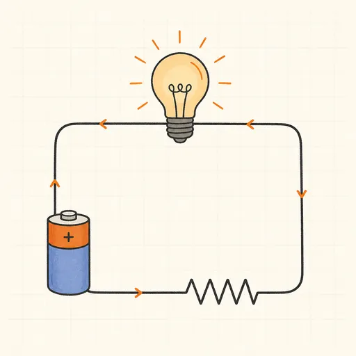
Ohm's Law Calculator
Any two of V, I, R, P — get all four.
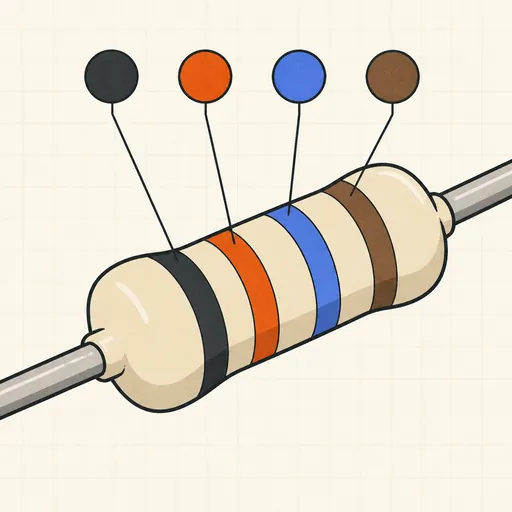
Resistor Color Code Calculator
4- and 5-band colors → value, or value → colors.
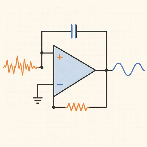
Active Filter Designer (Sallen-Key)
Butterworth, Chebyshev or Bessel — component values and Bode plot.
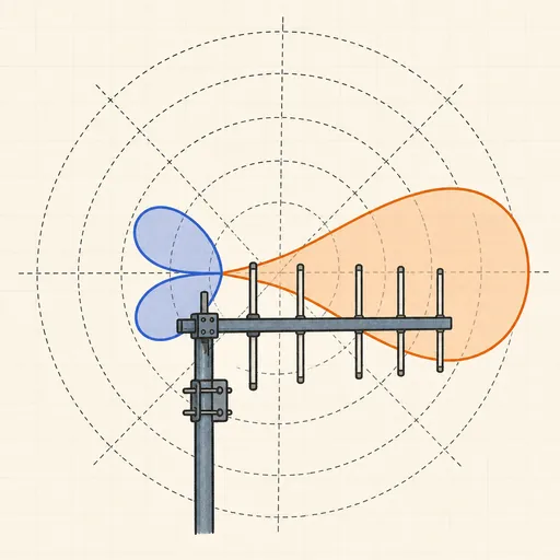
Antenna Radiation Pattern Explorer
Polar plots of dipoles, Yagis and phased pairs — see why more elements mean a narrower beam.
Capacitor Charge Calculator
RC time constant, charge curve and stored energy.

E-Series Resistor Solver
Best E12–E96 resistor or pair for any value or ratio.