Ohm's Law, Explained
Give any two of voltage, current, resistance, and power, and you can compute the other two. This guide shows the math, works a full example, and points out where the ideal equations stop matching your bench.
What Ohm's law says
Ohm's law relates three quantities in a resistor: the voltage across it, the current through it, and its resistance. In 1827 Georg Ohm measured wires and found that for many materials the current is proportional to the voltage. Double the voltage, double the current. The constant of proportionality is the resistance.
Here V is voltage in volts, I is current in amperes, and R is resistance in ohms (\Omega). One volt across one ohm pushes one ampere. That is the whole relationship.
A quick hook. You have a 12 V battery and a 100 Ω resistor. The current is I = 12 / 100 = 0.12 A, or 120 mA. Nothing else needed. Now suppose you also want to know how much heat that resistor makes. That is where the power law comes in, and this calculator handles both at once.
When it applies and when it does not
Ohm's law is a property of the component, not a law of the universe. A device is ohmic when its resistance stays roughly constant as voltage changes. Metal-film resistors, wire, and most PCB traces are ohmic over their rated range. Their voltage-current graph is a straight line through the origin, and the slope is 1/R.
Many parts are not ohmic. A diode drops about 0.7 V almost regardless of current, so its "resistance" changes wildly. An LED does the same near its forward voltage. An incandescent bulb has a cold filament resistance several times lower than its hot resistance, so its line curves. For those parts, use Ohm's law only for the resistor you place in series, not for the device itself. The LED series resistor calculator exists for exactly that reason.
Ohm's law does not include temperature, frequency, or time. A resistor that reads 100 Ω at room temperature may drift to 100.4 Ω when it heats up. Capacitors and inductors do not obey V = I \cdot R at all under changing signals; for a capacitor charging through a resistor, see the capacitor charge calculator.
The power law and the four-way triangle
Electrical power is the rate at which energy is delivered. For any two-terminal element it equals voltage times current.
P is power in watts. One watt is one joule per second. If 12 V drives 0.12 A, then P = 12 \times 0.12 = 1.44 W of heat in that resistor.
Because V = I \cdot R, you can substitute and get two more forms that skip a variable:
These four quantities (V, I, R, P) form a closed set. Fix any two and the other two are determined. That is why the tool offers four input modes: voltage and resistance, voltage and current, current and resistance, and voltage and power. Each pair reaches all four values through the equations above.
Rearranged for the value you want:
| Want | From V, R | From V, I | From I, R | From V, P |
|---|---|---|---|---|
| V | given | given | I R | given |
| I | V/R | given | given | P/V |
| R | given | V/I | given | V^2/P |
| P | V^2/R | V I | I^2 R | given |
A worked example with the demo values
12 V across 100 Ω
Use the default mode, voltage and resistance, with V = 12 V and R = 100 Ω. Follow the arithmetic:
- Current: I = V/R = 12/100 = 0.12 A, which is 120 mA.
- Power by the direct law: P = V \cdot I = 12 \times 0.12 = 1.44 W.
- Check with the resistance form: P = V^2/R = 144/100 = 1.44 W. Same answer.
- Check with the current form: P = I^2 R = 0.0144 \times 100 = 1.44 W. Same again.
All three power formulas agree, which is a good sanity check that you entered the numbers correctly. Note that the tool's other default fields (0.5 A and 10 W) belong to the other input modes; in voltage-and-resistance mode only V and R are read.
A practical follow-up: a 1.44 W dissipation means you should not use a common 1/4 W (0.25 W) resistor here. It would run far past its rating and likely burn. You need at least a 2 W part, and sizing up to 3 W gives margin.
See how the line bends when the load changes
For a fixed resistor the current rises linearly with voltage. The chart below plots current against voltage for a 100 Ω resistor. The slope is 1/R = 0.01 A per volt, so at 12 V you read 0.12 A.
Power, on the other hand, grows with the square of voltage. Double the voltage and the heat quadruples. At 12 V the resistor dissipates 1.44 W; at 24 V it would dissipate 24^2/100 = 5.76 W, four times as much. This is the single most common cause of released magic smoke.
Reading the results correctly
Keep your units consistent. The formulas assume volts, amperes, ohms, and watts. If you enter current in milliamperes by mistake, every derived value is off by a factor of 1000. Convert first: 120 mA is 0.12 A, and 4.7 kΩ is 4700 Ω.
Watch the size of the numbers. A result of 0.12 A reads more naturally as 120 mA. A resistance of 4700 Ω is 4.7 kΩ. The physics is identical; only the prefix changes.
When you compute a resistance and then buy a real part, the shops sell fixed values (the E12 and E24 series). Pick the nearest standard value above your calculated one for current-limiting jobs, so you never exceed the target current. The resistor color code calculator turns a value into bands and back.
Common mistakes
Confusing series and parallel. Ohm's law applies to one resistor at a time. Two 100 Ω resistors in series make 200 Ω; in parallel they make 50 Ω. Combine first, then apply V = I \cdot R to the combination.
Assuming the source holds its voltage. A real battery has internal resistance. A 9 V battery with 2 Ω internal resistance driving a 10 Ω load does not put 9 V across the load. The current is 9/(2+10) = 0.75 A, so the load sees 0.75 \times 10 = 7.5 V, not 9 V. Under heavy load the terminal voltage sags.
Ignoring power rating. The calculator gladly reports 10 W in a resistor. That is a physical warning, not just a number. Match the part's wattage rating to the computed power with margin.
Treating a divider output as fixed. A two-resistor divider gives one voltage with no load attached, but drawing current changes it. Use the voltage divider calculator to see how the load affects the output.
Frequently asked questions
How do I find current if I only know voltage and power?
Use I = P/V. A 60 W bulb on 120 V draws 60/120 = 0.5 A. Its resistance is V^2/P = 14400/60 = 240 Ω when hot.
Why do three power formulas give the same answer?
They are the same equation with V = I \cdot R substituted in. Starting from P = V \cdot I, replacing V gives I^2 R, and replacing I gives V^2/R. If your three results disagree, you mistyped an input.
Is Ohm's law true for AC?
For a pure resistor, yes, using RMS values: V_{rms} = I_{rms} \cdot R. For capacitors and inductors you need impedance, which depends on frequency, so a single fixed resistance no longer describes them.
What resistance does zero current imply?
If current is zero at a nonzero voltage, resistance is effectively infinite: an open circuit. The formula R = V/I divides by zero, which is the math telling you no path exists.
How much does temperature change a resistor?
A typical metal-film resistor drifts about 50 to 100 parts per million per degree Celsius. A 100 Ω part warming 40 °C shifts by roughly 100 \times 100 \times 10^{-6} \times 40 = 0.4 Ω, about 0.4 percent. Small for most work, but real for precision measurement.
Related tools
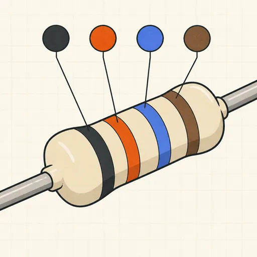
Resistor Color Code Calculator
4- and 5-band colors → value, or value → colors.
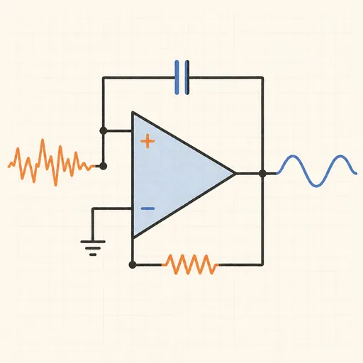
Active Filter Designer (Sallen-Key)
Butterworth, Chebyshev or Bessel — component values and Bode plot.
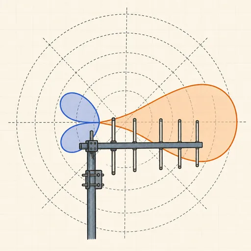
Antenna Radiation Pattern Explorer
Polar plots of dipoles, Yagis and phased pairs — see why more elements mean a narrower beam.
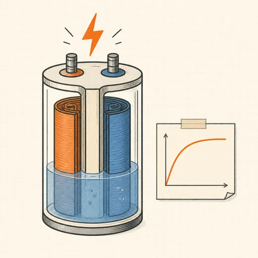
Capacitor Charge Calculator
RC time constant, charge curve and stored energy.

E-Series Resistor Solver
Best E12–E96 resistor or pair for any value or ratio.
LED Series Resistor Calculator
The right resistor for any LED and supply voltage.