Capacitor Charge, Explained
After reading this you can predict how a capacitor's voltage rises when it charges through a resistor, find the time constant, and calculate the energy it holds at any moment.
What the RC charging curve is
Connect a resistor and a capacitor in series to a battery, close a switch, and the capacitor does not jump to the battery voltage. It fills up gradually. The resistor limits how much current can flow, and current is the only way charge reaches the capacitor plates. The larger the resistance or the larger the capacitance, the slower the fill.
A concrete hook: a 100 µF capacitor charging through a 1 kΩ resistor from a 5 V supply reaches about 3.16 V after 100 ms, not 5 V. It needs roughly half a second to look "full" to a voltmeter. That single delay is the basis of timers, debounce circuits, power-supply soft starts, and the reset pulse in many chips.
The shape of the rise is an exponential approach. It climbs fast at first, then slows as the capacitor voltage nears the supply. The rate of approach is fixed by one number: the time constant.
When this calculation applies, and when it does not
The formula here assumes three things. The supply voltage is constant. There is a single resistor in series with a single capacitor. The capacitor starts fully discharged at 0 V.
Those assumptions cover a large fraction of real circuits: an RC filter fed from a regulated rail, a delay network on a reset pin, a sample-and-hold input. They do not cover everything.
If the capacitor already holds some charge when the switch closes, or if the supply itself sags under load, the simple curve is wrong. A partly charged capacitor starting at V_0 follows V(t) = V_s - (V_s - V_0)e^{-t/RC}. This tool assumes V_0 = 0.
Also assume the resistor is a real resistor, not the internal resistance of a wire or a switch. If you rely on stray resistance, the time constant is whatever the parasitics happen to be, and that varies part to part.
The formula and where it comes from
Start with two facts. The current through the resistor is set by the voltage across it, by Ohm's law: I = (V_s - V)/R, where V is the capacitor voltage. And the capacitor relates charge to voltage by Q = C V, so current, the rate of charge flow, is I = C \, dV/dt.
Set the two expressions for current equal and you get a differential equation whose solution is the charging curve:
Here V_s is the supply voltage in volts, t is time in seconds, R is resistance in ohms, and C is capacitance in farads. The product RC has units of seconds and is called the time constant.
One time constant is the time to close 63% of the gap to the supply. That figure comes straight from the math: at t = \tau, the exponent is -1, and 1 - e^{-1} = 0.632. After 2\tau you are at 86.5%, after 3\tau at 95.0%, and after 5\tau at 99.3%. Engineers treat 5\tau as "fully charged" for practical purposes.
Keep units consistent. Microfarads and kilohms are convenient because they cancel: 1 kΩ × 1 µF = 1 ms. So 1000 Ω × 100 µF is 0.1 s, or 100 ms, without touching a calculator.
A worked example with the demo numbers
5 V, 1 kΩ, 100 µF, read at 100 ms
These are the tool's default values. Follow the four steps.
- Time constant: \tau = R C = 1000 \times 100 \times 10^{-6} = 0.1 s, which is 100 ms.
- The read time equals one time constant: t/\tau = 100/100 = 1. So the exponent is -1.
- Voltage: V = 5(1 - e^{-1}) = 5 \times 0.6321 = 3.161 V.
- Energy stored at that voltage: E = \tfrac{1}{2} C V^2 = 0.5 \times 100 \times 10^{-6} \times 3.161^2 = 4.996 \times 10^{-4} J, about 0.50 mJ.
The fully charged energy, if you waited past 5\tau, would be 0.5 \times 100 \times 10^{-6} \times 5^2 = 1.25 mJ. At one time constant you hold 40% of the final energy even though you are at 63% of the final voltage, because energy scales with voltage squared.
Explore the time constant
Reading and interpreting the results
Three numbers matter when you look at output.
- Time constant
- The natural clock of the circuit. Compare your read time to it. If your time is much less than \tau, the capacitor is barely charged. If it is above 5\tau, treat it as full.
- Voltage at time t
- The instantaneous plate voltage. For a timer that trips at a threshold, this is what you compare against the threshold. A logic input flipping at 2.5 V on a 5 V system trips at t = -\tau \ln(1 - 2.5/5) = 0.693\,\tau, so about 69 ms for a 100 ms time constant.
- Stored energy
- Half the capacitance times voltage squared. This tells you how much a discharge can deliver, and how much a large capacitor bank could dump into a short circuit.
The table below shows the standard milestones for the demo circuit. Notice the voltage percentages are fixed by the number of time constants and do not depend on the actual values of R or C.
| Elapsed | t / τ | Fraction of Vs | Voltage (V) | Energy (mJ) |
|---|---|---|---|---|
| 100 ms | 1 | 0.632 | 3.161 | 0.4996 |
| 200 ms | 2 | 0.865 | 4.323 | 0.9347 |
| 300 ms | 3 | 0.950 | 4.751 | 1.129 |
| 400 ms | 4 | 0.982 | 4.908 | 1.205 |
| 500 ms | 5 | 0.993 | 4.966 | 1.233 |
Common mistakes
The unit slip is the most frequent error. A "100" typed as farads instead of microfarads inflates the time constant by a factor of one million. Always confirm that RC comes out in a plausible range: microfarads and ohms give microseconds to seconds for most hobby circuits.
The second mistake is assuming the capacitor reaches the supply voltage instantly for logic timing. It never mathematically reaches V_s; it only approaches it. Design thresholds around 3\tau to 5\tau, not at the asymptote.
The third is thinking the resistor changes the stored energy. It does not. The final energy is \tfrac{1}{2} C V_s^2 regardless of R. A curious fact: while charging, the resistor dissipates exactly the same energy as the capacitor stores, another \tfrac{1}{2} C V_s^2, so a simple RC charge is only 50% efficient no matter how you pick R.
That 50% figure is exact and independent of R. For the demo circuit, the capacitor keeps 1.25 mJ and the 1 kΩ resistor turns another 1.25 mJ into heat during charging.
Related tools
The charging current at any instant is I = (V_s - V)/R, a direct application of the Ohm's Law Calculator. If your resistor is a physical part with color bands, decode or choose its value with the Resistor Color Code Calculator. When a capacitor feeds a divider network, the Voltage Divider Calculator tells you the steady-state output. And if the same supply also drives an indicator, size its current-limiting resistor with the LED Series Resistor Calculator.
Frequently asked questions
How long until a capacitor is fully charged?
There is no exact "full" moment because the approach is asymptotic. Use 5\tau as the practical answer: at that point the voltage is 99.3% of the supply. For the demo circuit, 5\tau = 500 ms.
Does a bigger resistor store more energy?
No. Stored energy is \tfrac{1}{2} C V^2, which contains no R. A bigger resistor only slows how fast the energy arrives. The final energy for a 5 V, 100 µF capacitor is 1.25 mJ whether R is 100 Ω or 100 kΩ.
What is the time constant in plain words?
It is the time to close 63% of the gap between the current voltage and the supply. In each further time constant you close 63% of the remaining gap. It is the same idea as a half-life, just measured at the 63% mark instead of 50%.
Why is the voltage after one time constant 63% and not 50%?
Because the number is set by 1 - e^{-1}, and e^{-1} = 0.368, so the fraction charged is 0.632. The 50% point falls a little earlier, at t = 0.693\,\tau, which is 69 ms for a 100 ms time constant.
Can I speed up charging without changing the final voltage?
Yes, lower R or C. Cutting the 1 kΩ resistor to 500 Ω halves the time constant to 50 ms, so the capacitor hits 3.16 V in 50 ms instead of 100 ms, and still tops out at 5 V.
Related tools
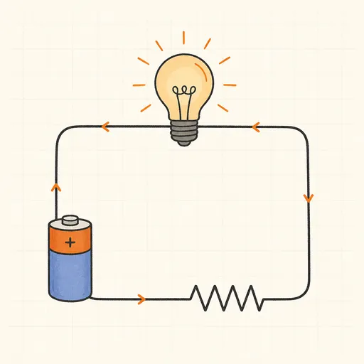
Ohm's Law Calculator
Any two of V, I, R, P — get all four.
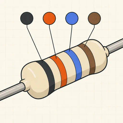
Resistor Color Code Calculator
4- and 5-band colors → value, or value → colors.
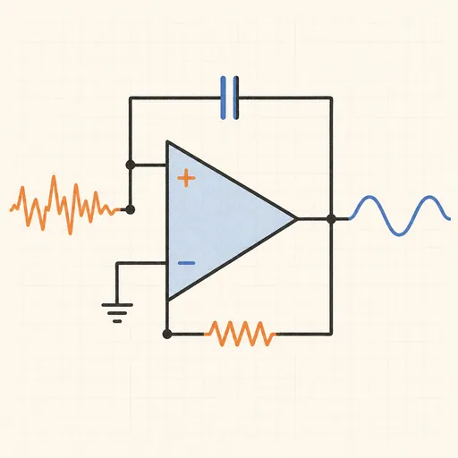
Active Filter Designer (Sallen-Key)
Butterworth, Chebyshev or Bessel — component values and Bode plot.
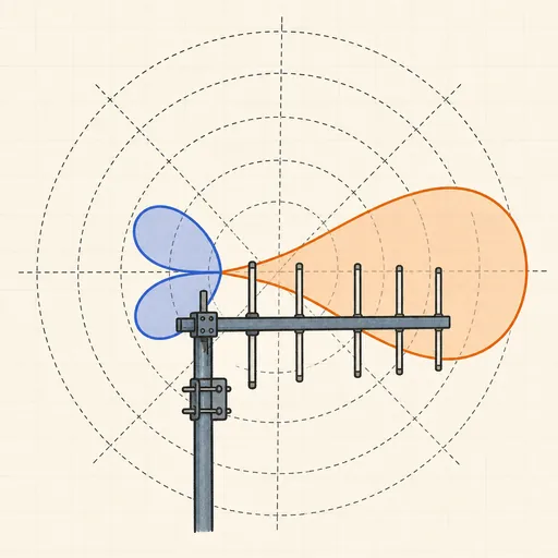
Antenna Radiation Pattern Explorer
Polar plots of dipoles, Yagis and phased pairs — see why more elements mean a narrower beam.
E-Series Resistor Solver
Best E12–E96 resistor or pair for any value or ratio.
LED Series Resistor Calculator
The right resistor for any LED and supply voltage.